Cost-Effective Spin Coater
A benchtop spin coater with closed-loop speed and acceleration control, built from catalogue parts for about ₹3,000.
Spin coating is how you get a uniform thin film onto a wafer: drop the solution in the middle, spin the substrate, let centrifugal force and evaporation do the rest. Film thickness falls as angular speed rises, so the machine has exactly one job — hold a commanded speed, and get to it along a commanded ramp.
The project set out to build an affordable laboratory instrument with control over both speed and ramp time. The prototype cost about ₹3,000 in parts; the project report compared it with commercial systems priced above US$2,000 at the time.
Measuring the speed
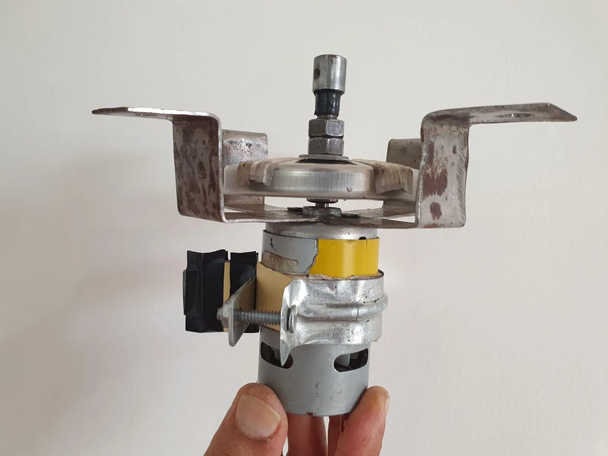
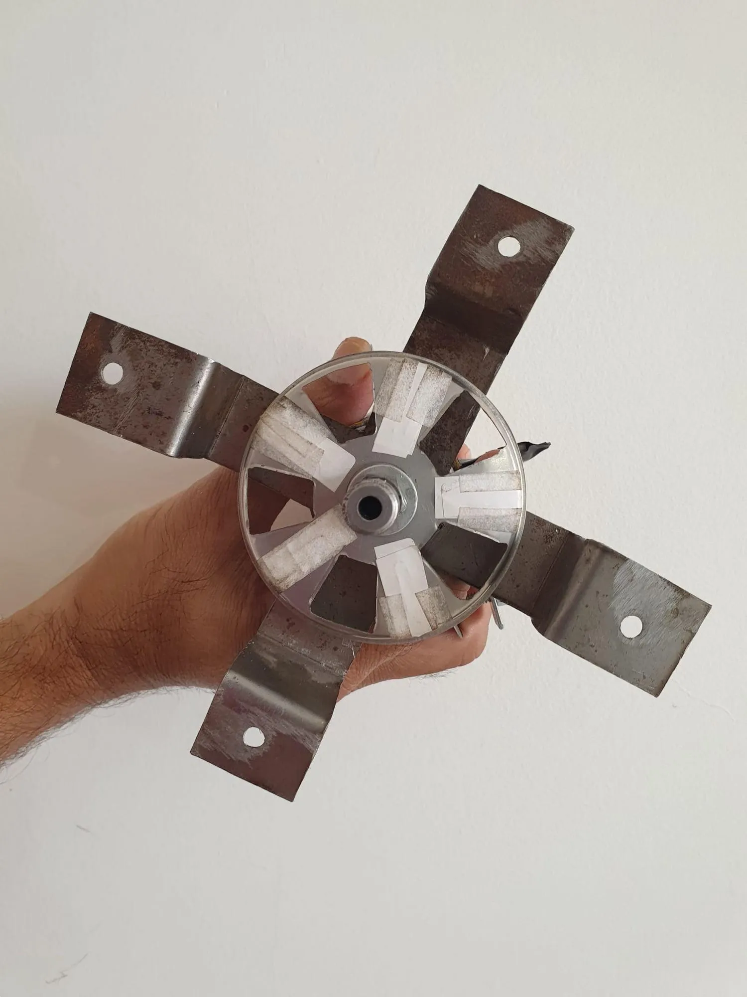
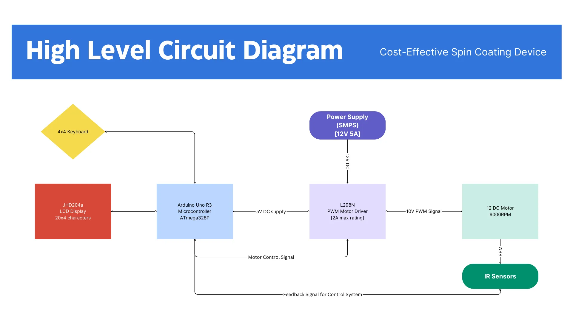
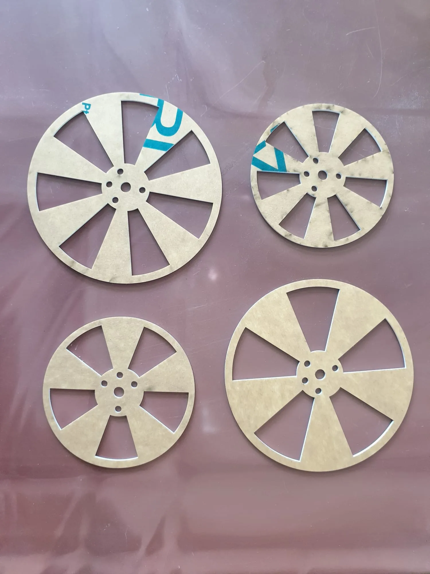
A slotted disc on the motor shaft passes between two infrared pairs. One counts slots; the second sits offset so the order of the two edges gives direction. That is the entire sensor.
It is also the noisiest part of the machine. The visible ripple in the plots is the IR signal, not the controller — with an external encoder substituted in, the ripple disappears and the ramp is smooth. A 25 kHz low-pass filter took some of it out; it did not take all of it out.
Why one PID controller was not enough
RPM against PWM duty cycle is not linear, and PID is a linear controller. Tuned for one operating point it misbehaves at another.
The fix is gain scheduling: linearise the system at several points — 1,000 RPM, 2,000 RPM, and so on — tune a controller for each, and switch between them as the setpoint moves. The load here is nearly constant, so a linear approximation holds well enough inside each band.
The acceleration problem, and the trick that solved it
Controlling acceleration directly was the part that did not work. Feeding acceleration error to a PID loop with PWM as the control signal produced large errors and real vibration — the same non-linearity, worse.
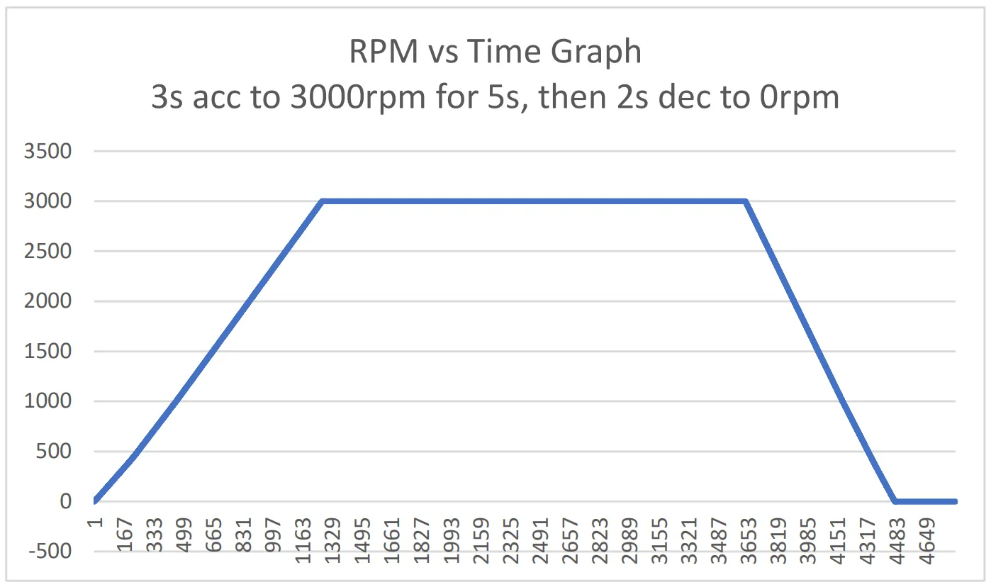
What worked was to stop controlling acceleration at all. Keep the loop on velocity error, and ramp the setpoint linearly, with the slope set to the acceleration you want. The controller only ever sees the problem it is good at, and the acceleration comes out as a consequence.
The measured ramp tracks the commanded one closely enough that the two lines overlap.
What it does
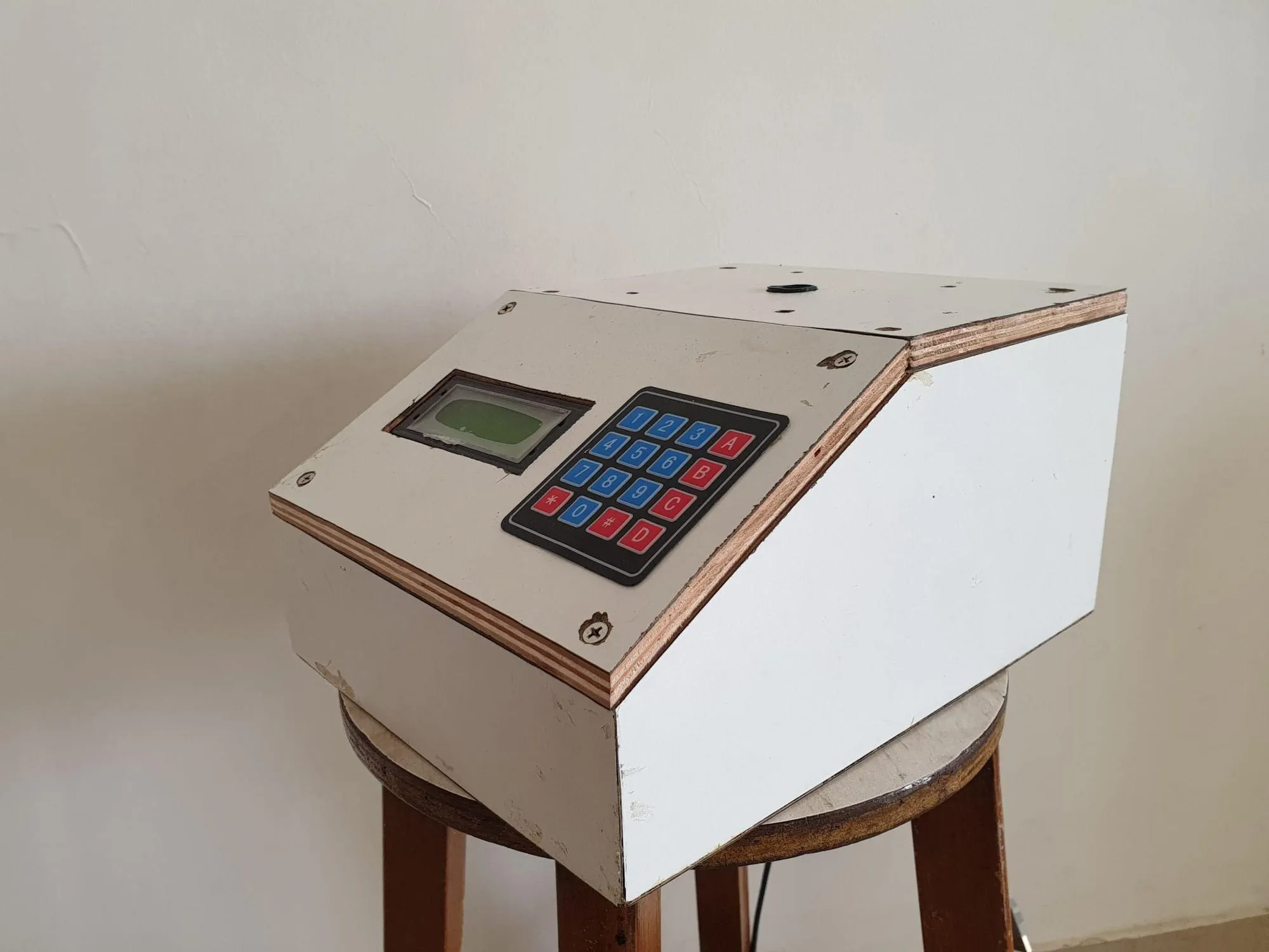
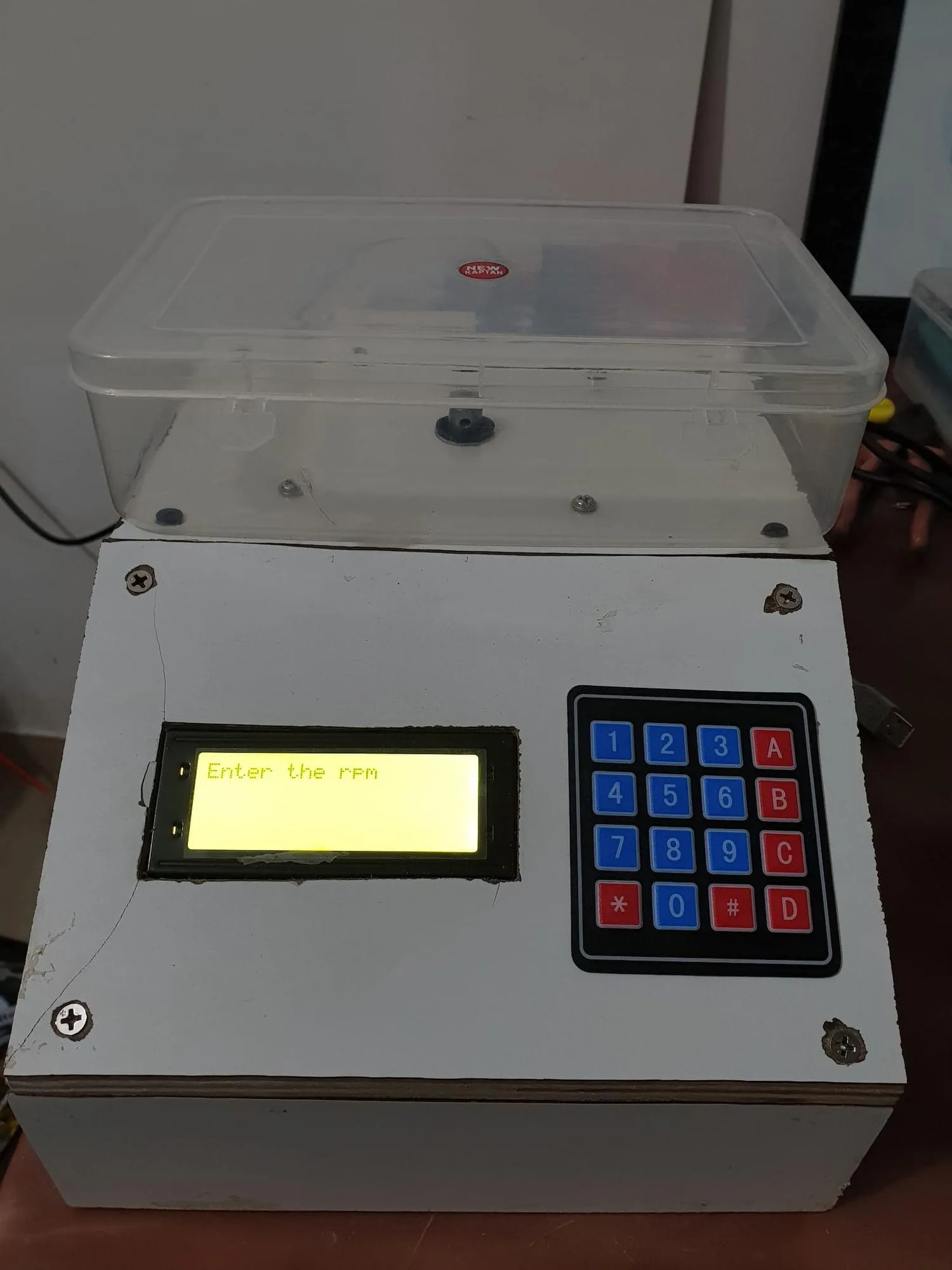
Across 500 – 5,000 RPM the error stays within ±25 RPM. Acceleration time, target speed, hold time and deceleration time are entered on the keypad; the firmware runs one step, and extends to multi-step recipes with small changes.
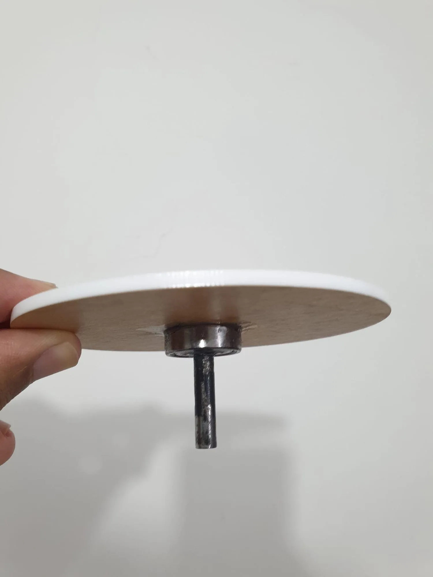
One thing worth recording because it is counter-intuitive: ball bearings on the motor shaft made things worse. They added friction and load without meaningfully reducing vibration, and removing them dropped no-load current from 1.2 A to 0.41 A.
Where it went
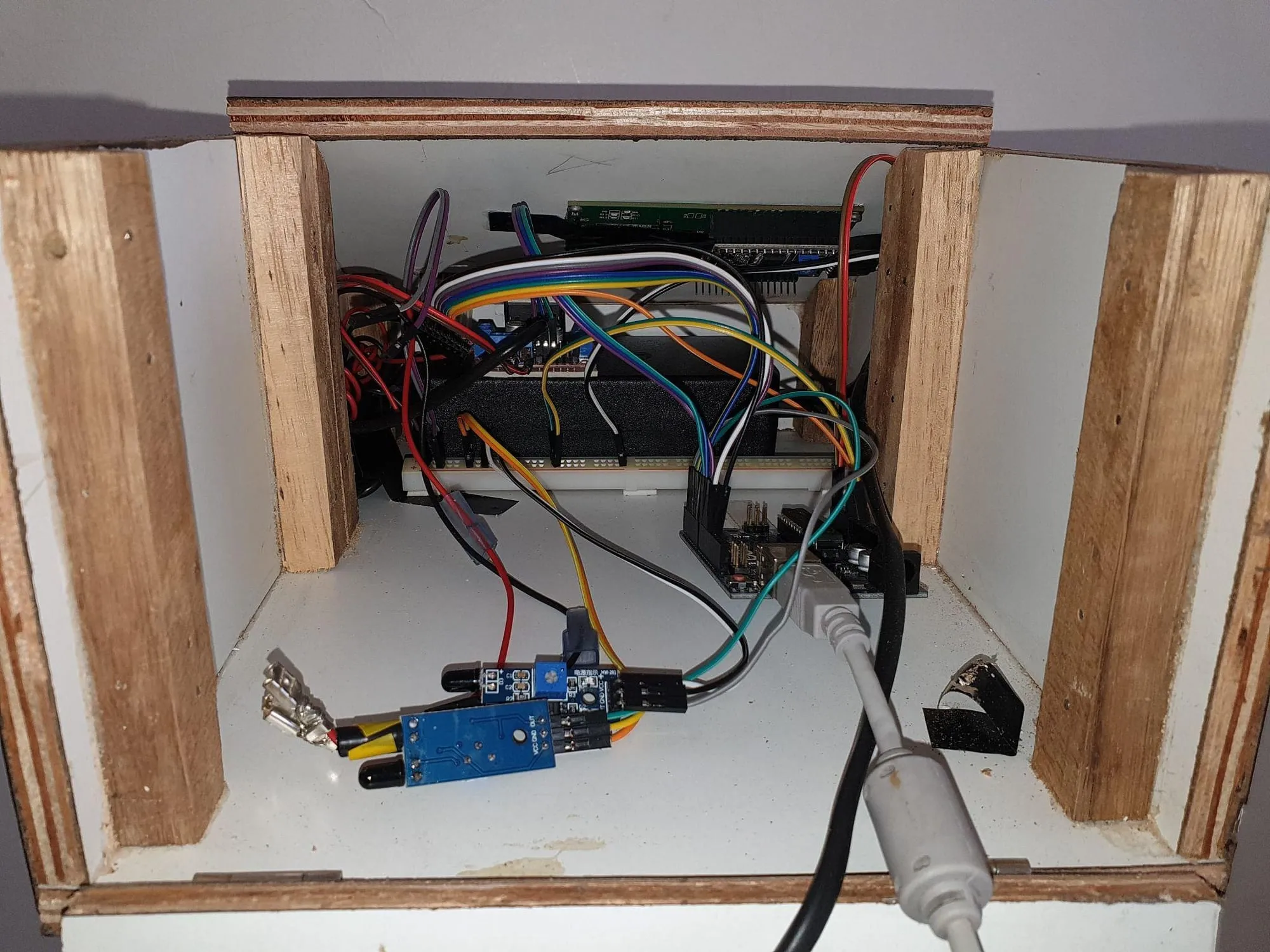
The report documents version 1 — the wooden box above. The machine has kept moving since, and the firmware changelog is the honest record of it:
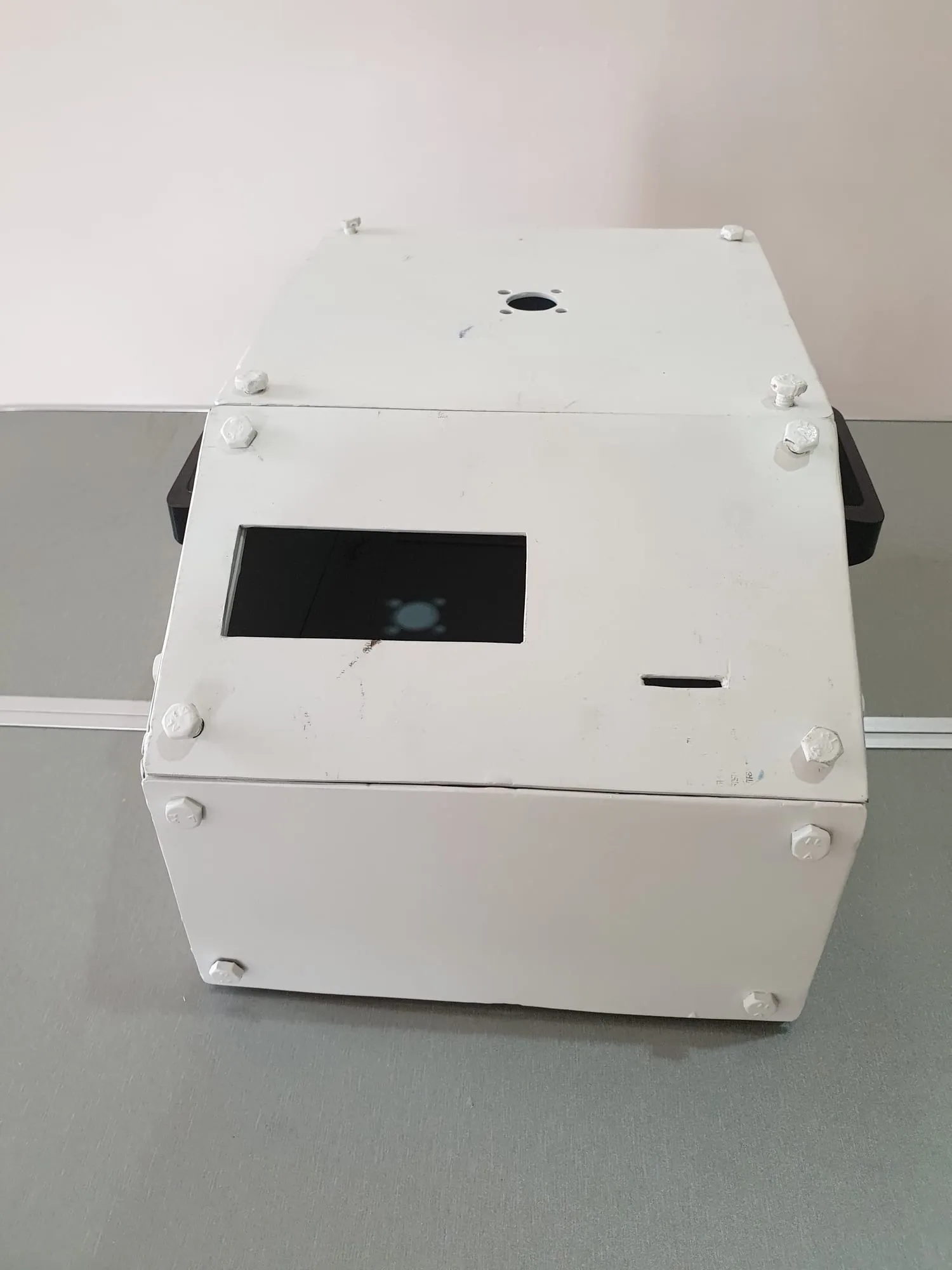
- v2.0 — metal box and frame, which cut vibration properly, and a higher-torque motor.
- v2.1 — play/pause, plus recalibration for better RPM accuracy.
- v2.2 – v2.3 — pause and resume during acceleration, with a configurable resume ramp.
- v3.0, planned — an ESP32 for two cores and Wi-Fi, a touchscreen UI, and a proper clamp for the wafer. It is held on with double-sided tape at present, because vacuum suction at this scale is genuinely hard.
Accuracy and range would both improve with a servo motor and an integrated encoder. Those are potential upgrades beyond the original low-cost design.
Gallery
0909